How to Borescope Your Cylinders: A Step-by-Step Guide (and How to Read What You Find)
If you read my last piece on oil analysis, you know how badly that one shook my confidence in the lab reports. Three years of clean oil analysis while both camshafts were quietly spalling underneath me. The borescope is what finally showed me what was actually going on.
That article was about why I bother with a borescope at all. This one is the actual how-to: the steps, the shot list, and what you’re supposed to be seeing when you look at each photo, because taking the pictures is honestly the easy part.
A compression check tells you air is leaking somewhere. It doesn’t tell you where, or how fast that leak is getting worse, or whether it’s a speck of lead sitting on a valve seat that’ll blow off on the next flight versus real erosion eating into the seat itself. A borescope shows you the actual surfaces.
You don’t need an A&P ticket to do this yourself. You need a decent scope, about 45 minutes to an hour for a six-cylinder engine, and enough discipline to do it the same way every time, because the real value shows up when you compare this year’s photos against last year’s. I do it at every oil change, right alongside pulling, cleaning, and gapping the spark plugs. The cowl is already off and the plugs are already out, so it costs you almost nothing extra to look.
What you need
Nothing exotic. This used to require shop-grade equipment costing thousands of dollars. Now it doesn’t.
- An articulating borescope, not a rigid one. You need at least 90 degrees of tip deflection to work into the valve pocket and around the cylinder wall. The $150–300 USB and WiFi scopes are fine for this. Don’t cheap out and grab a $29.99 potato camera off Temu, though. You get what you pay for, and a scope that can’t hold focus or throw enough light will bury the exact detail you’re inspecting for. Spend the money. I’ve used a couple of different ones in that $150–300 range and the image quality gap between them is smaller than the price gap would suggest. The one I reach for now is a Ralcam articulating borescope. Two things sold me on it: the articulating head is driven by a thumbwheel, so I can aim the tip into the valve pocket with one hand instead of fighting a fixed-angle probe, and it pairs directly to my phone over Bluetooth. That last part matters more than it sounds. There’s no SD card to pull and no card reader to hunt for. The shots land on my phone as I take them, already where I want them for labeling and archiving. Savvy Aviation, whose protocol this sequence is built on, tends to point people toward the Vividia line. You won’t go wrong there either. The important thing is that whatever you buy articulates and gets the images onto something you can save and compare.
- Some way to save and label images as you shoot them. Most scope apps let you snap and name on the fly. If yours doesn’t, screenshot and rename right away. Don’t wait until all six cylinders are done to sort out which photo is which.
- A ratchet, or just your hand on the prop, to rotate the engine between shots.
- Something to jot notes on. Anything that catches your eye mid-inspection, write it down. You will not remember it by cylinder six.
Before you touch a spark plug
Do all of this work with the applicable maintenance manuals and any other approved data open in front of you. Your engine manufacturer’s overhaul and maintenance manuals, the relevant service bulletins and instructions, and the airframe manuals cover the torque values, safe practices, and wear limits that apply to your specific engine. Nothing in this article substitutes for them. Read what the manufacturer says about your powerplant before you start, and defer to it wherever it differs from what you read here.
Mixture to idle cutoff. Mags off. Key out of the ignition switch entirely, not just switched off. Then act like none of that happened. Every time you put a hand on the prop, treat it like it could fire. It shouldn’t be able to, but that’s not the moment to find out you were wrong.
Pull the top plugs on the cylinder you’re working. That gives you a clean shot down into the chamber, and it lets the piston move freely when you turn the prop by hand instead of fighting compression on that cylinder.
Work each cylinder start to finish before moving to the next one. Turning the prop moves every piston at once, so if you bounce between cylinders you’ll lose track of which one is in what position, and you’ll end up repeating shots or skipping them.
The 11 shots
This sequence is close to what’s become the standard in the borescope world, largely because of the work Savvy Aviation has done popularizing it. I stick to the same order because after doing this on my own airplane more times than I’d like to admit, it covers everything that actually matters, and it’s repeatable enough to build a real photo history from.
One habit that pays off on every shot: angle the tip slightly off the surface so the LED doesn’t reflect straight back into the lens. Too much glare washes out the metal and hides the exact detail you’re trying to read.
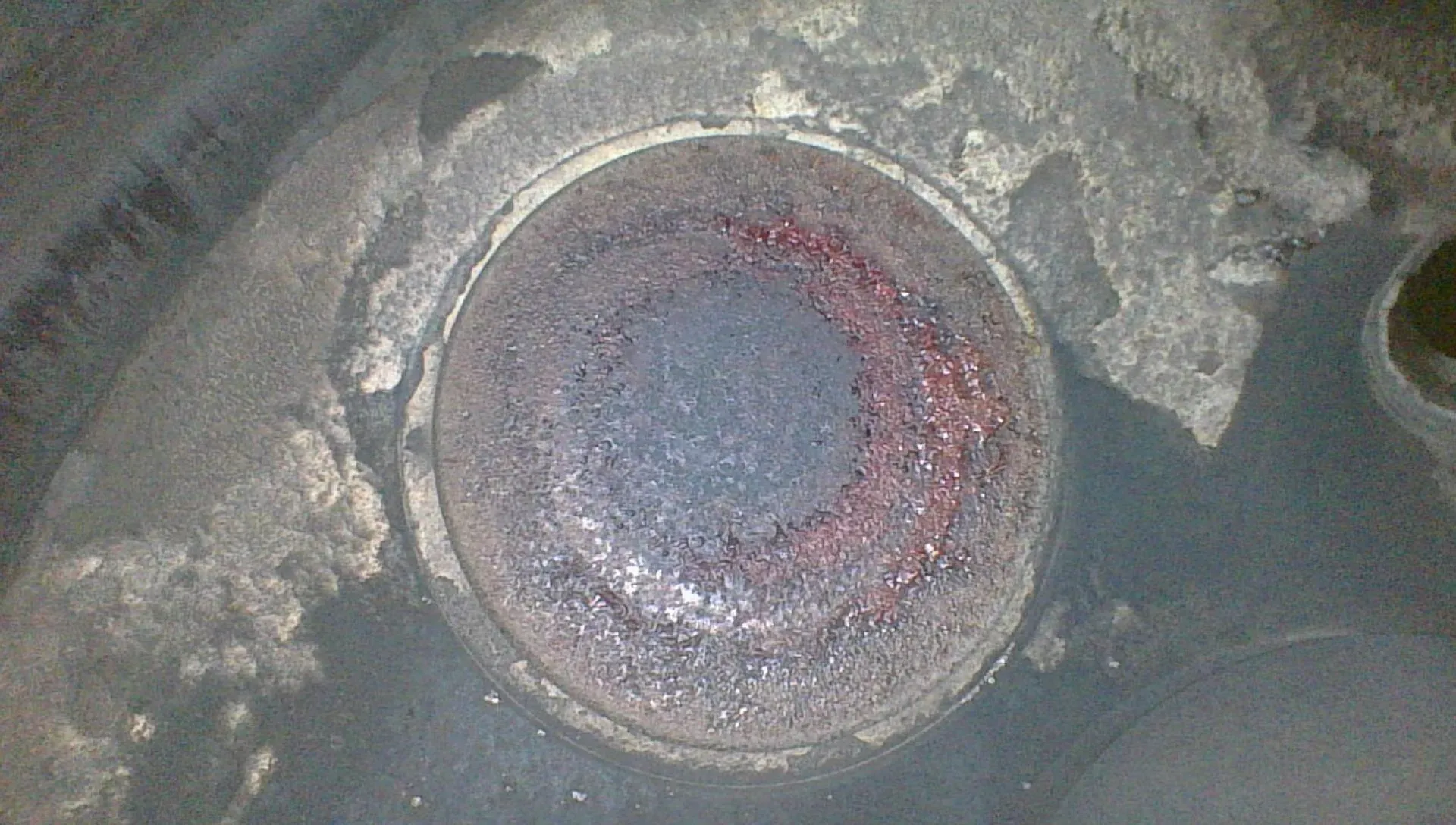
Piston crown. Rotate the prop until that piston sits at the bottom of its stroke so you get the whole crown in frame. This is your baseline on combustion health: the color and pattern of the deposits, and whether the crown is evenly coated or scrubbed clean in spots.
Exhaust valve head, closed. Straight shot down at the valve face while it’s seated. This is the hottest-running part in the cylinder, at rest.
Intake valve head, closed. Same framing, other valve. It should look noticeably cleaner than the exhaust valve, because it’s bathed in cool fuel-air on every intake stroke and never has hot exhaust gas rushing past it.
Exhaust valve seat and face, wide open. Rotate the prop until the valve is fully open, then get the scope positioned so the valve’s seating face is fully visible. You want to see the chamfer on the seat and the ring where the valve face contacts it. This is the one most people give up on too fast because it’s fiddly to line up. It’s also the most important photo on the list, the only one that shows you where the seal actually happens.
Exhaust valve stem and guide. With the valve still held open, slip the scope tip in past the seat and look down the stem toward the guide.
Intake valve seat and face, wide open. Same technique as the exhaust seat, other valve.
Intake valve stem and guide. Same technique as the exhaust stem, other valve.
Cylinder wall, four quadrants. Bring the piston back down near the bottom of the stroke and take four wall shots spaced roughly 90 degrees apart, at 12, 3, 6, and 9 o’clock, so between them you’ve covered the full circumference. This is the tricky set, because the plug hole doesn’t line up with the cylinder axis, so you can’t just insert the scope and spin it in place. Go in, get oriented, back out a little, rotate the scope body, go back in. Expect more attempts here than on the valve shots, especially on your first engine.
The 11-shot protocol run on one cylinder of my left engine: piston crown, both valve heads closed, both valve seats wide open, both stems and guides, and four cylinder-wall quadrants. Click any image to enlarge.
That’s 11 photos per cylinder. Name the files as you go: cylinder number, then view, like 3-piston.jpg, 3-exhaust-seat.jpg, 3-wall-3oclock.jpg. You won’t remember which blurry wall shot belongs to which cylinder once you’re four cylinders in.
Once you’ve got the hang of it, figure five to ten minutes a cylinder. First time through, give yourself more room than that and don’t get frustrated when the seat shots take four or five tries.
Reading the photos
Taking the pictures is the mechanical half of this. Reading them is the half that actually protects your engine, and it’s the part most people never really learn. Everything below comes from my own engines.
Piston crown
Normal is a fairly even, dry, grayish-tan to light brown coating. That’s combustion deposit, and it’s expected. Worth a second look: wet or oily-looking deposits, which usually mean oil is getting into the chamber past worn rings or guides, and shiny scrubbed-looking bare patches, which can point to detonation or a hot spot. A scattering of small lead specks is normal on 100LL. A heavy, caked, uneven buildup is worth tracking over the next inspection or two.
Left: a fairly typical crown, even, dry, gray-tan deposit. Right: a crown from another cylinder on the same airplane, with heavier, more uneven, scrubbed-looking patches. Neither is an emergency, but the difference is exactly what you want a photo history to track.
Here’s the wet version, from a different cylinder on the same airplane:
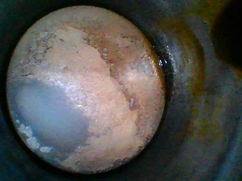
That’s oil past the rings: a dark, wet, oily-looking crown instead of a dry tan one. On its own it’s not an emergency, but it’s exactly the kind of thing you want a photo history to track, because rising oil consumption and a crown that keeps getting wetter tell the same story from two directions.
Valve heads, closed
The intake valve should look cleaner than the exhaust, for the reason above: it’s cooled by the incoming fuel-air charge on every intake stroke and never has hot exhaust gas rushing past it.
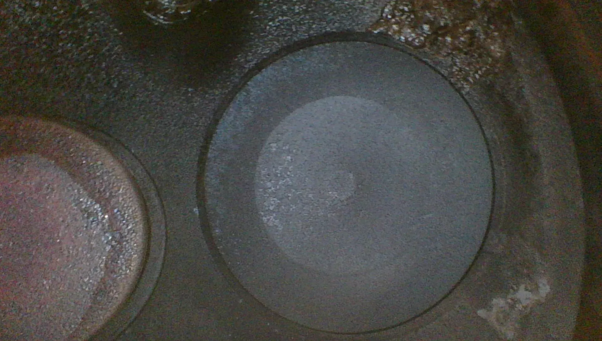
What matters here isn’t how much deposit is present. It’s whether the pattern is even. A uniform ring of deposit around the valve head means it’s sealing consistently. A pattern heavier on one side, or a dark streak radiating out from one point on the edge, means gas has been leaking past the seat at that spot on every cycle. That’s the earliest sign of valve erosion, and it shows up here before it ever moves a compression number.
Valve seats and faces, wide open
This is where you decide what that cylinder actually needs. A healthy exhaust valve face shows an even, concentric pattern. Mechanics call it the bullseye, or the “burnt pizza” look: continuous, roughly circular bands of color with no interruption. That evenness is what you’re after. It means the valve is seating all the way around and rotating properly, so every part of the face takes its turn against the seat and sheds heat evenly.
Left: a healthy exhaust valve face from my engine, an even concentric bullseye, exactly what you want. Right: a distressed exhaust valve from a 2024 inspection on the same aircraft, where the even concentric pattern has broken up into a mottled, washed-out patch. Both are exhaust valves. That difference is what the whole inspection is looking for.
The photo on the right is what you’re watching for, and it’s worth understanding why it looks like that. The tell isn’t the exact hue of any one patch, it’s that the even concentric pattern has broken up. That mottled, washed-out area is a spot running hotter than the rest of the face and no longer making clean, uniform contact all the way around. Color does matter in one specific way, though: a green or otherwise odd tint on an exhaust valve is a classic dead giveaway of one that’s overheating and starting to burn. On this valve, the culprit was the rotocoil, the little rotator cap on top of the valve stem whose job is to index the valve a few degrees on every cycle so it doesn’t sit in exactly the same spot each time it closes. When the rotocoil fails and the valve stops rotating, one arc of the face keeps landing on the same part of the seat, loses good contact, and can no longer dump its heat into the seat and out through the cylinder head. Heat that can’t escape stays in the metal, and the face starts to burn.
On a Continental, the fix at this stage is straightforward: replace the rotocoil and lap the valve in place. You spin the valve against its seat with a little lapping compound between them, a fine abrasive that grinds the two surfaces back into an even, matched contact ring. Done early, that’s an in-place repair without pulling the cylinder. Left alone, a burning valve keeps eroding until a piece of the valve head can fracture and break off. If that happens with the engine running, the liberated chunk gets hammered between the piston and the head, and that’s a catastrophic, engine-out failure. This is exactly the kind of finding that justifies the whole exercise: you can catch it as a discoloration in a photo, months before it becomes a compression problem and years before it becomes an emergency.
Flying behind a Lycoming? The playbook is different. Lycoming’s weak point is the valve guide, not the seat, so the standard check is the Service Bulletin 388C “wobble test,” which measures how much the valve stem rocks in the guide, at a minimum every 400 hours. A guide that’s wearing tight can often be reamed back to spec in place, without pulling the cylinder (Service Instruction 1425A). A guide that’s gone loose means the cylinder comes off. And a Lycoming valve that’s actually burned generally isn’t a lap-in-place fix the way a Continental is; it usually costs you a jug. The same borescope habit applies either way: watch the exhaust valve for uneven heat coloration and catch it early.
Not everything on a seat is that serious. A chunk of lead or carbon resting on the seat is common and usually not a big deal. It often clears on the next flight or two, and if it doesn’t, an in-place lapping fixes it. What’s not benign is metal loss: a scalloped or eroded edge on the valve face, a burned streak cutting across the seat, or visible pitting. That’s a finding you bring to your mechanic rather than photograph and move past.
Valve stems and guides
Look for even coloration along the stem and no visible play as the valve moves through the guide. Heavy, uneven carbon buildup necking down around the guide is a classic precursor to a sticking valve, worth noting even when it isn’t urgent.
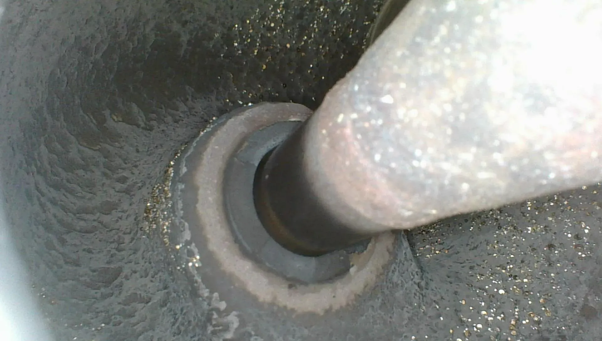
That’s a guide on my right engine that’s starting to show its age. You can see the valve guide itself deteriorating, with heavy, crusty deposit building up right where the stem rides in it. It isn’t a stuck valve, but it’s the direction a stuck valve comes from, and it’s exactly the kind of thing that means nothing in isolation and a lot next to a photo of the same guide a year from now.
Cylinder walls
You want to still see the cross-hatch honing pattern, the fine diamond scoring machined into the wall at the factory. Those grooves aren’t cosmetic, and it helps to picture what they actually are. In cross-section the honed surface is a row of tiny sawtooth peaks and valleys. The valleys hold a film of oil against the wall so the rings and piston keep gliding. The peaks are what the rings ride on.
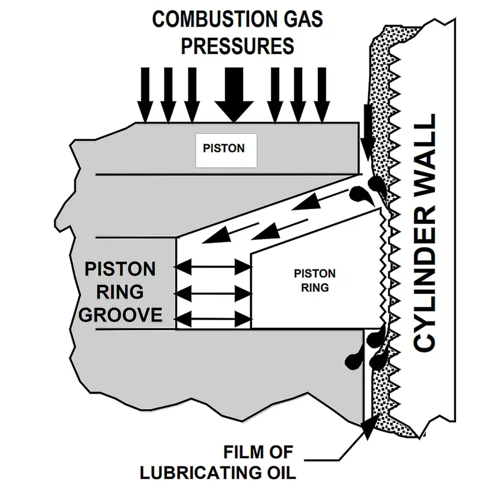
Combustion pressure does more than push the piston down. It gets in behind the top ring and forces it against the wall, and the sawtooth texture keeps a film of oil under the ring so it seals and slides instead of scuffing.
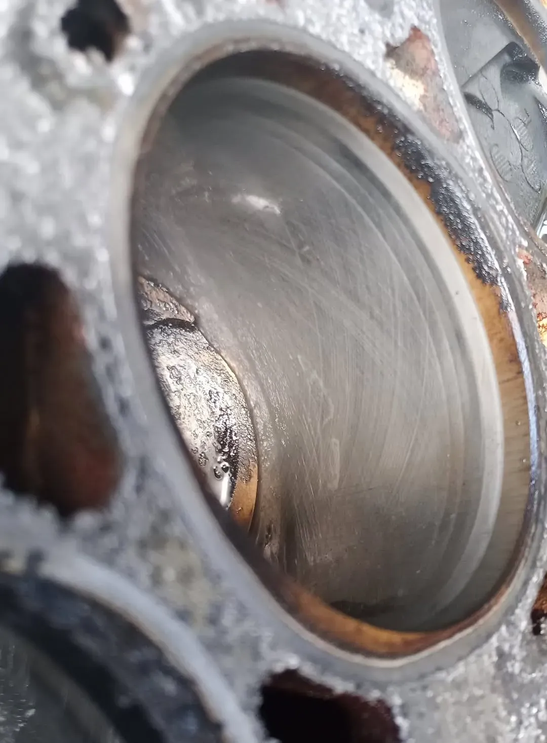
That’s a good hone: you can still see the cross-hatch worked into the wall, exactly the pattern you’re looking for. (It’s an automotive cylinder, standing in until I can borescope the fresh hone in my new jugs.)
Break-in is really the process of wearing those peaks in. Under enough power and cylinder pressure, the rings knock the sharp tops off the peaks and flatten them into a bearing surface, while the valleys stay open to hold oil. That’s why a fresh cylinder wants power, not babying. Break it in too gently and the peaks never wear down. Instead the oil bakes into a hard layer on top of the cross-hatch, the rings end up gliding on that baked glaze instead of the metal, and the grooves stop holding any oil. That’s glazing. A glazed wall can’t do its job, which shows up as high oil consumption and rings that never seal, and the usual fix is to re-hone and break the cylinder in all over again.
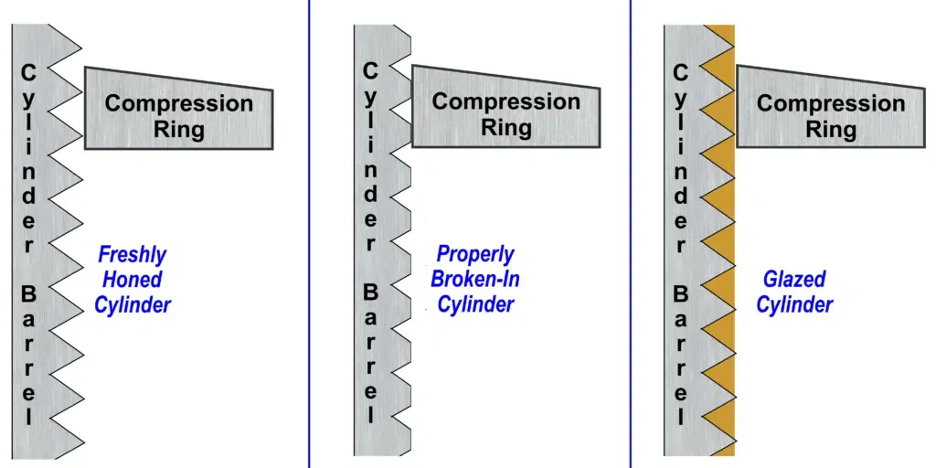
Those same three states, drawn in cross-section.
Diagrams courtesy of Savvy Aviation.A wall can also polish smooth the slow way, over hundreds of hours, as the cross-hatch simply wears from a strong pattern down to a ghost of itself and finally to a mirror finish. Either way, every wall shot you take is asking the same question: how much of that pattern is left.
Two wall quadrants from my engines. The cross-hatch is faded. You can still make out a ghost of the honing pattern, but these walls have clearly worn from their factory finish. Comparing wall shots year over year is how you catch this trending toward full glazing.
Beyond the honing pattern, watch for vertical scoring, which usually traces back to debris or a broken ring, and fine dark freckling, which is corrosion pitting from an engine that sits too long between flights. One isolated scratch usually isn’t significant. The same marking showing up in more than one quadrant is worth paying attention to.
One kind of vertical scoring deserves its own mention: piston pin scuffing. Most of these engines use a full-floating piston pin, a steel tube the piston pivots on that isn’t locked in place. What keeps it from walking sideways into the cylinder wall is a soft aluminum plug pressed into each end of the pin. Those plugs are sacrificial. They ride against the wall and are meant to be softer than it is. When a plug wears down or works loose, the hardened steel end of the pin starts dragging on the wall, and steel on steel cuts. Lycoming saw enough of this on cylinder kits from the mid- and late-1990s to issue service instructions over it, and Continentals aren’t immune.
In the scope it doesn’t look like a fine ring or debris scratch. It’s heavier and brighter, a set of vertical gouges running up and down the wall on the side the pin has migrated toward, cutting straight through the cross-hatch. It almost always comes with metal in the oil filter. This is not a watch-it-next-year finding. Scoring like this goes straight to your mechanic, and the filter and screen are the fastest way to confirm what’s happening.
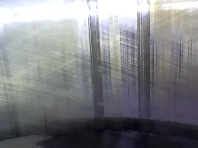
That’s what it looks like when the pin has reached the wall: hard vertical scoring cut up and down the cylinder where the steel pin end dragged, instead of an even cross-hatch.
Where this fits with oil analysis
This connects back to the camshaft issue I wrote about last time. Oil analysis is still useful. I run it every oil change, and it’s genuinely good at catching gradual trends in wear metals over months and years. But it’s an indirect measurement of a system that isn’t uniform. It can only tell you about whatever happened to be suspended in that particular sample. A borescope isn’t indirect. You’re looking straight at the part.
The strongest setup runs all three checks together instead of leaning on one: oil analysis for wear-metal trends over time, filter inspection for the large particles a lab sample won’t catch, and the borescope for a direct look at the parts neither of those can show you. They cover different blind spots.
A few things I got wrong the first time
- I rushed the valve seat shots because they’re annoying to line up, and those turned out to be the two most useful photos I skipped taking properly.
- I inspected right after shutdown once, while everything was still hot, and spent more time being careful not to burn myself than actually looking at anything. Let it cool first. There’s no rush.
- I didn’t label anything on my first inspection. Ended up with about forty unsorted images from a six-cylinder engine and spent longer sorting them out afterward than the inspection itself took.
- I treated one good set of photos as the whole answer. It isn’t. One inspection tells you the condition on that day. It’s the comparison against last year’s set that tells you whether something’s stable, improving, or getting worse.
Build the archive, not just the inspection
The real value here isn’t any single year’s set of photos, it’s what you can see when you put this year’s next to last year’s. A valve that looks a little heavier on deposit than you’d like, on its own, might not mean much. The same valve next to a photo from a year earlier, showing how much that pattern grew, means a lot more. That’s why you shoot it the same way, in the same order, every time, instead of eyeballing cylinders once a year and calling it done.
None of this replaces your mechanic’s judgment. If a photo shows what looks like real erosion, pitting, or scoring, take it to your A&P. Don’t talk yourself out of it because the engine’s still running fine today. But showing up with an organized, well-lit set of photos instead of “cylinder 3 sounded a little rough last flight” makes that a much better conversation.
David Stites, MEI Multi-engine flight instructor and professional ferry pilot in the San Francisco Bay Area.
David Stites, MEI
Multi-engine flight instructor and professional ferry pilot in the San Francisco Bay Area.
Ready to Start Your Multi-Engine Training?
Contact me today to discuss your training goals and schedule your first lesson.
Get in Touch